Linear Standards, Distance and Angular Measurement by Linear Apparatus : An Overview
(Note that as the quoted sources are mostly written in old English the spelling of words differs from today.)
Introduction
Whether it be for the partitioning of land or the construction of infrastructure the need to have a common unit to define the distance from one point to another was a necessity. While different groups of people were insular their individual units of distance did not need to have a common basis. It was when these groups, however, started to come together that their individual disparate units of distance created confusion and a conversion or standardisation was sought to establish a comprehensible, usable system of distance. Even today the world has the Metric and Imperial systems noting that Imperial system in America today is called United States Customary Units (USCS). Nevertheless, conversion, within and between, these systems is standardised.
In the Beginning
The Greek philosopher Plato (circa 427-348BC) founded the Platonist school of thought and the Academy, the first institution of higher learning in the western world. Plato, among others, refused to admit anyone into his school, that had not been first entered in the mathematics, especially geometry and arithmetic. In his work Phaedrus he stated that the Egyptian Thoth, god of the moon, wisdom, writing, hieroglyphs, science, magic, art, and judgment, invented numbers and arithmetic.
Understandably, the agricultural system of the Egyptians required the individual farmer to have knowledge of his land to sow. But it seems that it was the river Nile's annual flooding, which either washed away any boundary marks or covered them with mud, that saw the measuring of land develop into a professional and honoured practise. From Egypt, this art was brought into Greece by Thales. Nevertheless, the aspect of Egyptian civilisation that demonstrated their measuring capabilities was their infrastructure notably the pyramids.
The Egyptian Harpedonaptae (Surveyors or Rope-Stretchers shown in image below) used a rope that was treated to hold its length. The rope was stretched taut between stakes and then rubbed with a mixture of beeswax and resin. Some ropes were graduated by knots tied at intervals. Although disputed, the Egyptians most significant knotted rope had 12 knots. When arranged into a 3-4-5 configuration they had a right angle triangle, from which lines at a right angle could be established. (Many would recognise the 3-4-5 configuration as being Pythagoras’ Theorem but it existed in many cultures, by many names, for many years. Pythagoras is believed to have learned of the methodology during his studies in Egypt and developed the mathematics behind the theorem).
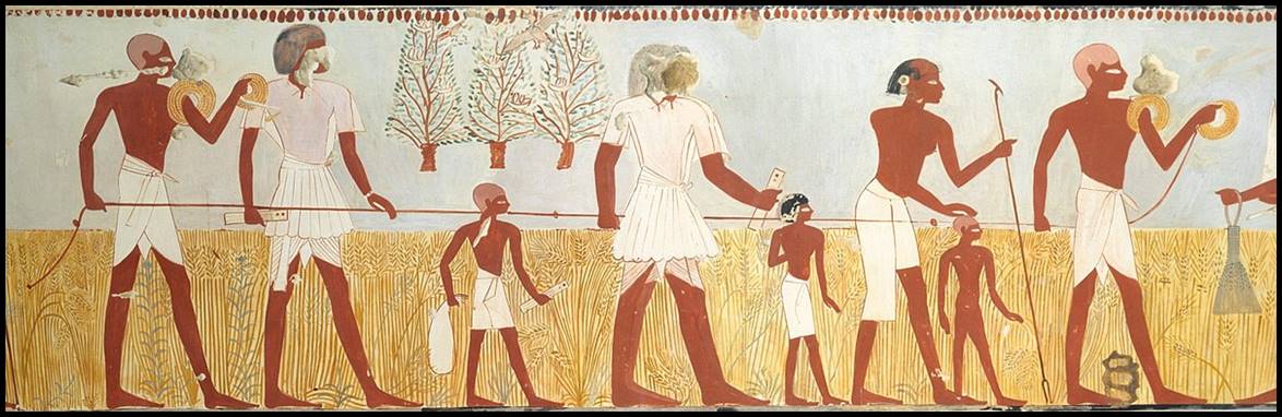
Egyptian Harpedonaptae, with their knotted rope, shown in Harvest Scenes from the Tomb of Menna, circa 1400 –1352BC.
Knotted ropes were used for measuring, by many ancient cultures. The Greek schoenus is referred to as a rope used to measure land; the Romans used a waxed rope for measuring distances; the Arabs used a rope smeared with wax after having been tautened twice. The following is from the 1728 Cyclopaedia by Ephraim Chambers : to obviate their [rope’s] inconsistencies…the little twists whereof the rope consists, be twisted contrary ways, and the rope dipped in boiling hot oil, and when dry, drawn through melted wax. A rope thus prepared, will not get or lose anything in length, even though kept under water all day, indicating the durability of a properly prepared measuring rope.
A documented use of rope to measure distance comes from the period In today’s Iraq under Caliph Al-Ma’mun (Abu al-'Abbas Abdallah Al-Ma'mun ibn Al-Rashid, 786-833AD). In about 827AD Al-Ma'mum requested his astronomers Al-Farghanl and Al-Khowarizmi to arrange the measurement of an arc of the meridian on the Plain of Sinjar near Baghdad. At Sinjar it is believed that the two measuring parties started from a central point, one going due north and the other due south, until their respective astronomical observations each indicated that they had travelled 1° of latitude. The linear distances were said to have been measured by using two ropes, each about 50 coudees (or cubits about 25 metres) long, placed so that they overlapped by half, and then leapfrogged with each other along the line. Each party then remeasured the work of the other and found it to be correct. The reason for overlapping half the ropes each time is thought to have been a way to easily check that the ropes were not deteriorating and giving a false length as well as keeping on a straight line.
When it came to setting out lines at right angles the Roman Agrimensores (measures of land) used a groma or gruma being a vertical staff with horizontal cross-pieces mounted at right angles on a bracket. Each cross piece had a plumb line hanging vertically at each end, thus with two plumb lines aligned in one direction, the other two plumb lines automatically established the direction of a line a right angles (please see image below). The instrument could be dismantled for portability. The groma is believed to have originated from about 400BC in Mesopotamia and was also used by the Greeks.
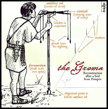
Image of a groma.
As civilisations came and went, expanded and contracted, an array of different systems of units were developed. Units like the Greek stade, Egyptian cubit, Chinese li, differed in length depending on where you were not only within a territory but over time as well. Various attempts at developing a conversion table have been found and some are described below.
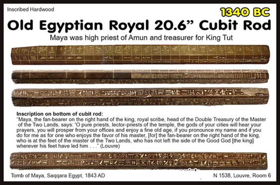
Rods also came into use to define a measuring unit. Usually of wood, their length represented the common cubit for a region, please see the table below. A cubit was the length of the forearm from the elbow to the tip of the middle finger. It was divided into the span of the hand or the length between the tip of little finger to the tip of the thumb (one-half cubit), the palm or width of the hand (one sixth), and the digit or width of the middle finger (one twenty-fourth). The Royal Cubit, which was a standard cubit enhanced by an extra palm, thus 7 palms or 28 digits long, was used in constructing buildings and monuments and in surveying in ancient Egypt.
|
Cubit |
Inches |
Notes |
|
Sumerian |
20.41 |
Of copper alloy, the Nippur (a Mesopotamian sacred city) Measuring Rod dated to circa 2650BC |
|
Mesopotamian |
21.0 |
|
|
Assyrian |
25.26 |
Circa 700BC |
|
Babylonian or Lagash |
19.53 |
|
|
Babylonian Trade |
17.58 |
|
|
Egyptian Royal |
20.62 |
Of hardwood, dated to 1340BC, please refer image below |
|
Egyptian Short |
18.24 |
|
|
Hebrew 1st Temple |
16.85 |
|
|
Hebrew 2nd Temple |
17.5 |
Also called Hebrew short |
|
Hebrew Long |
20.4 |
|
|
Arabic Hashimi |
25.6 |
|
|
Pergamon |
20.51 |
|
|
Salamis |
19.06 |
|
|
Persia |
19.69 |
|
|
Arabic Nil or Black |
20.28 |
Circa 9th century |
|
Persian or Beládi |
21.89 |
Circa 300BC |
|
Greek or Cyrenaican |
18.23 |
|
|
Roman |
17.48 |
|
|
England |
18.0 |
|
|
Thai |
19.69 |
|
|
|
|
|
|
Other |
|
|
|
Denmark |
53.15 |
Of oak, a rod from the Iron Age fortified settlement at Borre Fen, with markings that correspond closely to half a Doric Pous (a Greek foot) |
|
Denmark |
30.9 |
Of hazel, a rod from a Bronze Age burial mound in Borum Eshøj, East Jutland, which corresponds closely to the traditional Danish foot |
|
Holland |
N/A |
Of wood, Amsterdam cubit or ellemize. |
In the 16th century Danish astronomer Tycho Brahe (1546-1601) adopted a unit of measure the Passus Geometricus (Geometrical Pace of about 1.8 metres) such that 60 000 passus geometricus equalled a degree at the equator. The following 1771 table is an attempt at standardising the distance of a Mile and French League, then used by a number of European nations, in terms of the geometrical pace.
|
Mile |
Geometrical Paces |
|
Russian |
750 |
|
Italian |
1 000 |
|
English |
1 250 |
|
Scotland and Ireland |
1 500 |
|
Polish |
3 000 |
|
Spanish |
3 248 |
|
Germanic |
4 000 |
|
Danish |
5 000 |
|
Hungarian |
6 000 |
|
League |
|
|
Old French |
1 500 |
|
Small French |
2 000 |
|
Mean French |
2 500 |
|
Great French |
3 000 |
Apart from where the Roman Empire imposed its town grids and straight line roads for about 600 years, for the most part of what is now Europe and Asia, traditional, local rural methods perpetuated, which did not require a rigid measurable framework. Nevertheless, a system of measuring units necessarily evolved independently, of which some are described in the table of 1728 below. (Note that there are many versions of the ell, as originally understood to be a cubit, the combined length of the forearm and extended hand, but in some cases became an extended distance; the English ell was 1¼ English yards). The diagram below shows a selection of units, superimposed on Leonardo Da Vinci’s circa 1490 drawing Vitruvian Man, which being to scale meant that the units shown are in their proper historical ratios. A further table lists a wider range of measuring units expressed in their English inches and decimal equivalents to show their similarity and diversity. An even more extensive list of linear units of measurement, extracted from Brewster (1832), may be viewed via this link.
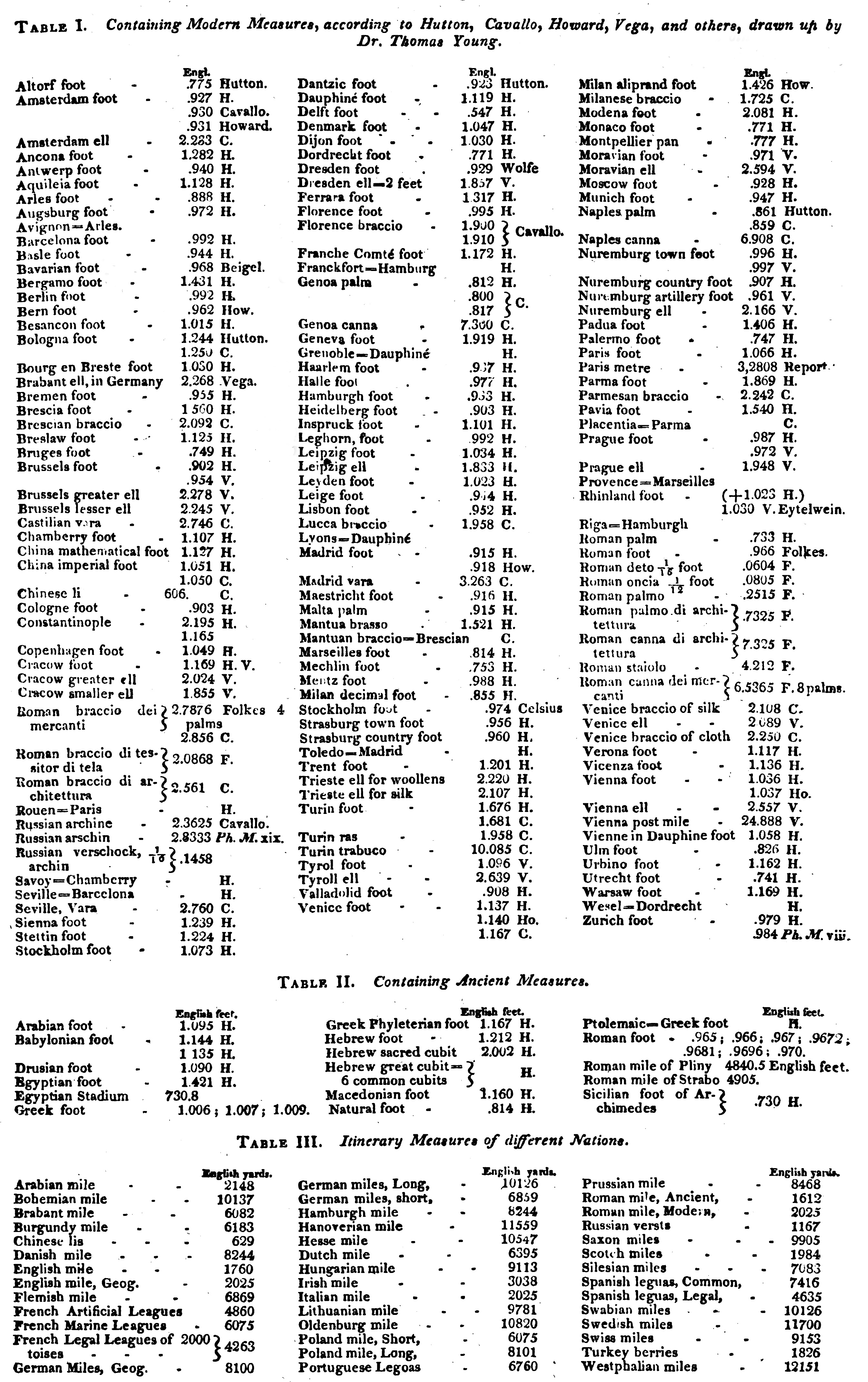
|
A List of Some Standard Measures, used for Commerce or Trade, in 1728 |
|
|
- |
The English Standard Measure was the Yard of 3 Feet. |
|
- |
The French Standard Measure was the Aune or Paris Ell except in Languedoc; in Marseilles, Montpellier, Toulouse, Provence and Guienne, they measured by the Canna. |
|
- |
The Standard Measure in Holland, Flanders, Sweden, a good part of Germany, many of the Hans-Towns, such as Dantzic and Hambourg and at Geneva, Francfort, etc was the Ell except that in all of these places its length differed from that of the Paris Ell. |
|
- |
The Italian Measure was the Braccio, Brace, or Fathom used in the States of Modena, Venice, Florence, Lucca, Milan, Mantua, Bologna, etc but of varying length. At Naples and in Sicily the Canna was used. |
|
- |
The Spanish Measure was the Virga or Yard, in some places called the Varra. The measure in Castille and Valencia was the Pan, Empan, or Palm, which together with the Canna, was used at Genoa. |
|
- |
The Portuguese Measure was the Covado. |
|
- |
The Piedmontese Measure was the Raso. |
|
- |
The Muscovite Measures were the Cubit, and the Arshin. |
|
- |
The Turkish and Levant Measure was the Picq. |
|
- |
Persia and some parts of the Indies used the Gueze. |
|
- |
Siam (Thailand) used the Ken. |
|
- |
Cambodia used the Coiang. |
|
- |
Japan used Ikiens. |
|
- |
The Pan was used on the Coasts of Guinea. |
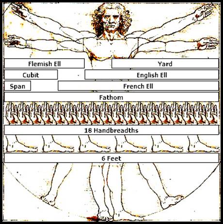
Selected units superimposed on Leonardo Da Vinci’s circa 1490 drawing, Vitruvian Man.
|
Linear Measure |
English Inches |
|
The English foot |
12.000 |
|
The Paris foot |
12.788 |
|
The Rhinland foot |
12.362 |
|
The Scots foot |
12.065 |
|
The Amsterdam foot |
11.172 |
|
The Dantzick foot |
11.297 |
|
The Danish foot |
12.465 |
|
The Swedish foot |
11.692 |
|
The Brussels foot |
10.828 |
|
The Lyons foot |
13.485 |
|
The Bologna foot |
14.938 |
|
The Milan foot |
15.631 |
|
The Roman palm used by merchants |
9.791 |
|
The Roman palm used by architects |
8.779 |
|
The palm of Naples |
10.341 |
|
The English yard |
36.000 |
|
The English ell |
45.000 |
|
The Scots ell |
37.000 |
|
The Paris aune (ell) used by mercers |
46.786 |
|
The Paris aune (ell) used by drapers |
46.680 |
|
The Lyons aune (ell) |
46.570 |
|
The Geneva aune (ell) |
44.760 |
|
The Amsterdam ell |
26.800 |
|
The Danish ell |
24.930 |
|
The Swedish ell |
23.380 |
|
The Norway ell |
24.510 |
|
The Brabant or Antwerp ell |
27.170 |
|
The Brussels ell |
27.260 |
|
The Bruges ell |
27.550 |
|
The brace of Bologna |
25.200 |
|
The brace used by architects in Rome |
30.730 |
|
The brace used in Rome by merchants |
34.270 |
|
The Florence brace used by merchants |
22.910 |
|
The Florence geographical brace |
21.570 |
|
The varra of Seville |
33.127 |
|
The varra of Madrid |
39.166 |
|
The varra of Portugal |
44.031 |
|
The covado of Portugal |
27.354 |
|
The ancient Roman foot |
11.623 |
|
The Perfian arish |
38.364 |
|
Small pike of the Turks at Constantinople |
25.576 |
|
Large pike of the Turks at Constantinople |
27.920 |
The Introduction of National Standards of Length
From medieval times in France the royal units of length were based on the Toise, and in particular the Toise de l'Écritoire, the distance between the fingertips of the outstretched arms of a man. Said to be introduced in 790 by Emperor Charlemagne (800–814), it in turn was based on existing Byzantine and ancient Roman measures.
Prior to 1668 the length of the Toise (not quite 2 metres) of Paris was defined by an iron standard fixed to the outside of the Grand Châtelet built circa 1130. Please refer to the figure below. Due to deformation occurring in the pillar to which the standard was attached, the now distorted standard was replaced in 1668 by the Toise du Châtelet. The Toise du Châtelet remained the French standard until 1776 when the metre was introduced.
The metre was initially defined as one ten millionth of the distance from the Equator to the North Pole. To establish this distance mathematically, the French sent a survey team north to then Lapland and another south to then Peru, essentially as far north and south that was accessible at that time. In 1735, the Toise of Châtelet was used to calibrate an iron standard for each survey team to take with them to ensure the consistency and accuracy of their measurements. The iron standard taken to Peru became known as the Toise du Perou (Peru) and later in 1766 the Toise of Peru became the official standard of the Toise in France and was renamed as the Toise of the Academy (Toise de l'Académie). In the first decades of the 1800s, direct copies of the Toise of Peru were made for various agencies and uses. Unfortunately, during all this handling of the standard it was lost and copies of the standard were then used as the reference for the true length of the Toise.
Even while the results of the two surveys were being finalised, an indicative equator-pole distance emerged. From this result several platinum bars of slightly different lengths were manufactured so that as soon as the accepted survey value emerged for the metre, the bar whose length was closest to that value could be selected. Subsequently, this bar was placed in the National Archives on 22 June 1799. This standard metre bar became known as the Metre des Archives. This reference bar was later replaced in 1889 with a platinum-iridium bar.
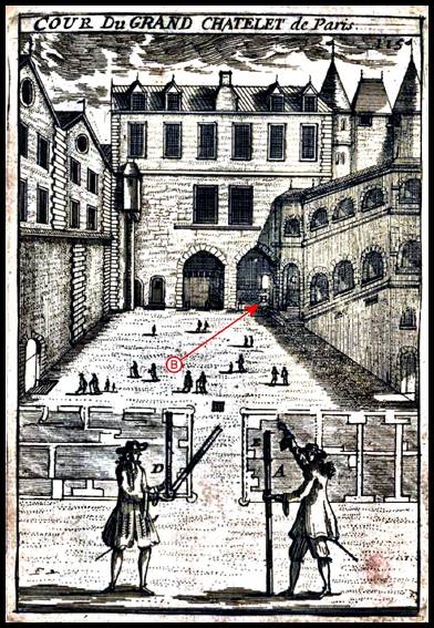
Illustration of the Grand Châtelet showing a straight (A) and folding (D) measuring rod, each of one toise, in front of the location of the standard iron toise located at (B) at the foot of the grand staircase in the courtyard of the Grand Châtelet.
Parallel activity on the adoption of a linear standard occurred in England. No alteration of the Saxon measures was made following the Norman Conquest. King William 1 (circa 1028-1087, the Conqueror) at his coronation in 1066 confirmed that they be just exactly as the good predecessors have appointed. The same confirmation was given by succeeding sovereigns and by Magna Carta in 1215.
By custom, a hide was the amount of land that a team of eight oxen could plough during the annual ploughing season but was also deemed to be the amount of land required to support a peasant household. Around the time of the Domesday Book a hide was nominally 120 acres being 120 times the amount of land which a ploughteam of eight oxen could plough in a single day and not 120 units of areal extent. The areal extent of a hide remains undetermined but estimates indicate that a hide was generally less than 50 areal acres. The Domesday Book which was the record of the great survey of England, commenced by William 1 in 1085, thus gave the extent of all land holdings in historical Saxon terms.
By contrast linear measurement continued to be based on a mile as determined by the Romans as being 1 000 paces. A foot was traditionally the length of a man's foot, and inch came from the Latin word unci, meaning one-twelfth. A rod Is believed to have originated from the typical length of a medieval ox-goad [also pole or perch from Latin pertica (a pole or measuring rod), and French perche] and an acre was the amount of land tillable by one man behind one ox in one day (the traditional acres were long and narrow due to the difficulty in turning the ox driven plough). The furlong then came from a furrow long, or the distance that could be ploughed by an ox without a rest. As early as the 9th century, however, the furlong was regarded as the equivalent of the Roman stadium, which was 1/18 of a Roman mile, later being defined as 1/8 of an English mile.
Then from 1495 to 1587, the Winchester Units, affirmed by King Henry VII (1485-1509) were adopted, followed by the use, from 1588 to 1825, of the Exchequer Standards, as defined by Queen Elizabeth 1 (1533-1603). The standard of the English Yard has been carefully maintained, such that from 1305 to the present, the deviation in the length of the yard has been rather less than 1 in 1000, as shown in the table below, by a number of standard bronze yards still in existence, including the primary standards of Henry VII, 1497, and Elizabeth, 1588.
|
Present Location of Standard |
Millimetres (*) |
|
Winchester Exchange Standard, stamped in the reign of Henry VII and again for Elizabeth, at Westgate Museum, Winchester. |
-1.0 |
|
Westminster Exchequer Standard, of Henry VII, 1497, at Science Museum, Kensington. |
-0.94 |
|
The Merchant Taylors' Company's "Silver" Standard Yard, stamped in reign of Henry VII circa 1497, (actually an iron rod totally encased in silver, engraved with the arms of the Company), at The Merchant Taylors' Hall, London. |
+0.15 |
|
Westminster Exchange Standard, of Queen Elizabeth, 1588, standard until 1824, at the Science Museum, London. |
-0.25 |
|
(*) : Difference from present Imperial Standard Yard |
|
From 1588 to 1824 the Exchequer Standard of Elizabeth was the length of the official English yard. Copies were made to permit the comparison with local regional yard standards and such copies were kept at the Tower of London. These were all end measures with coarse subdivisions of feet and inches, meaning that the whole length of the bar from end to end, constituted the length of the yard. Later, the Line standards, had fine lines inscribed upon such bars indicating the magnitude of the yard.
In 1742 the Royal Society of London, required a more accurately subdivided linear measure than that of Queen Elizabeth, for scientific purposes. George Graham (1673-1751) was commissioned to undertake the work with the assistance of Jonathan Sisson (1690 -1747) the London instrument maker. This was done on two finely engraved flat brass bars 42” long, ½” wide and ¼” thick on each of which were carefully marked off the lengths of the existing Tower Standard Yard made in 1720, and Elizabeth's Exchequer Standard Yard of 1588. The two bars were sent to France to the Academie Royale des Sciences at Paris where the length of the French half-Toise was marked on the bars. One bar was retained in Paris and the other returned to the Royal Society in London. This was the origin of having scientifically constructed linear standards to preserve the ancient established standards of both England and France.
Under George IV (1762-1830) there was a complete reorganisation of Imperial weights and measures in 1824, which became effective on 1 January 1826. A new Primary Standard Yard was made by John Bird (1709-1776), being a bronze bar, about 1" square in section and some 39" long, with small gold studs let in to the surface, 36" apart, on each of which was a fine dot point to mark the extremities of the yard. The Yard was defined in the 1824 act as the distance between a pair of lines etched in gold plugs inserted in a bronze bar in the custody of the clerk of the House of Commons, which had been designated a standard yard in 1760. The new yard was actually the standard that had been commissioned by the Royal Society in 1742, which in turn had been based on the earlier Elizabethan standard. This new standard bar was ordered to be deposited in the House of Commons and confined in a recess in one of the stone walls for safe keeping, only to be taken out every ten years for comparison. The Houses of Parliament were destroyed by fire in 1834, however, and the standard yard and other standards were damaged. Fortuitously, the foresight of Thomas Frederick Colby (1784-1852), had seen the manufacture of two iron yard standards in 1827-1828.
Colby, then British Major General and Director of the Ordnance Survey, devised initially for the triangulation of Ireland, a dual arrangement of brass and iron, which he called a compensation bar. The Colby compensation bar or just Colby bar, as his apparatus became known, was used for trigonometric baseline measurements. To ensure the operation of his compensating bars Colby also had two ten feet iron standard bars manufactured. These two bars were to serve as a permanent record of the length of the compensation bar and of the base measurements when undertaken at a temperature 62°F. Further, Colby had two three feet (1 yard) bars, manufactured. Colby’s yard standards then permitted the Imperial Yard to be re-established. Forty bars were cast in 1845, the one that best matched the length of the existing yard thus became the new Imperial Standard Yard. The next best bars were approved as Parliamentary Copies and sent to England's cities and colonies, including those of Australia.
The Royal Commission of 1843-1855, was charged with the design, construction and an exhaustive series of comparisons with existing standards to produce a new Primary Standard of the Yard along with four Parliamentary copies. Manufactured in 1845, they were legalised by an 1855 Act which stated :
the form adopted for the standard of length and for all the copies thereof is that of a solid square bar, thirty-eight inches long and one inch square in transverse section, the bar being of bronze or gun metal; near to each end a cylindrical hole is sunk (the distance between the centres of the two holes being thirty-six inches) to the depth of half an inch; at the bottom of this hole is inserted in a smaller hole a gold plug or pin about one tenth of an inch in diameter, and upon the surface of this pin there are cut three fine lines at intervals of about the one hundredth part of an inch transverse to the axis of the bar, and two lines at nearly the same interval parallel to the axis of the bar; the measure of length is given by the interval between the middle transversal line at one end and the middle transversal line at the other end, the part of each line which is employed being the point midway between the longitudinal lines; and the said points are herein referred to as the centres of the said gold plugs or pins.
The well holes at each end containing the gold plugs/pins were protected when not in use by push-in type bronze caps.
The Primary Standard Yard was engraved from left to right :
Copper 16 oz., Tin 2½, Zinc 1. Mr Baily's Metal
No. 1. Standard Yard at 62.00°F
Cast in 1845
Troughton & Simms London
The four Parliamentary copies were similarly engraved except for their numbers and the temperatures at which they are equal in length to the Primary Standard, as shown in the table below.
|
Parliamentary Copy |
Held by |
|
No. 2 Standard Yard at 61.94°F |
The Royal Mint |
|
No. 3 Standard Yard at 62.10°F |
The Royal Society of London |
|
No. 4 Standard Yard at 61.98°F |
Houses of Parliament, Westminster |
|
No. 5 Standard Yard at 62.16°F |
The Royal Observatory |
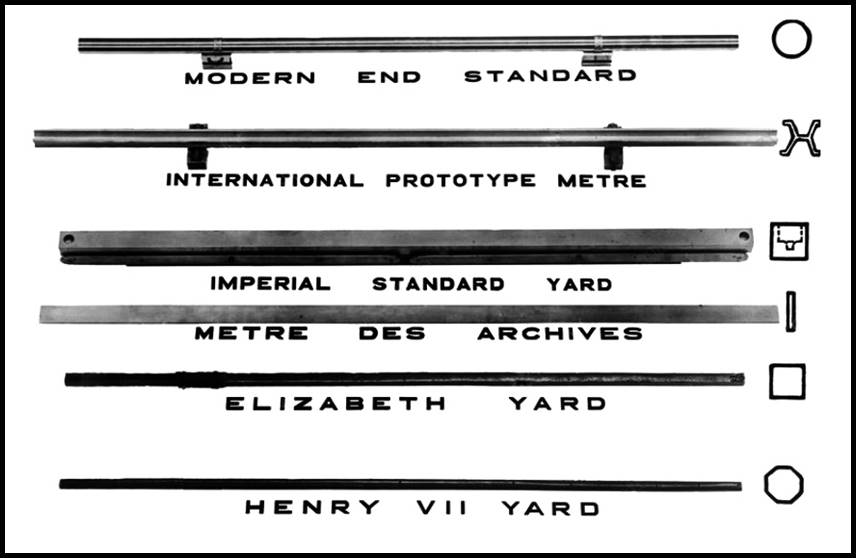
Historical length standards, courtesy National Physical Laboratory, Teddington, UK;
Standards established for the Yard and the metre, along with their cross-sections (right). The Winchester Units of Henry VII, Yard (1497) and the Exchequer Standards of Elizabeth 1, Yard (1588) were followed by the Imperial Standard Yard (officially recognised in 1855). The Metre Des Archives (platinum, standard from 1799 to 1889) was followed by the International Prototype Metre (iridium-platinum, standard from 1889 to 1960). Modern end standards are cylindrical bars of carbon steel accurately machined to precise lengths and used to measure larger lengths.
The Weights and Measures Act of 1824 and the Act of 1878 established the British Imperial System on the basis of precise definitions of selected existing units. The table below refers.
|
Imperial Units of Linear and Land Measure |
|
|
A Table of Linear Measure |
|
|
12 Inches |
1 Foot |
|
3 Feet |
1 Yard |
|
5½ Yards, 16½ feet |
1 Rod, Pole or Perch |
|
4 Rods, 22 Yards, 66 Feet or 100 Links |
1 Chain |
|
10 Chains or 40 Rods |
1 Furlong |
|
8 Furlongs, 80 Chain, 320 Rods, 1760 Yards, or 5280 Feet |
1 Mile |
|
|
|
|
A Table of Land Measure |
|
|
5½ Yards |
1 Pole or Perch |
|
30¼ Square Yards |
1 Square Perch |
|
40 Square Perches |
1 Rood of Land |
|
4 Roods, 10 Square Chains or 160 Square Perches |
One Acre of Land |
|
|
|
|
Other used herein |
|
|
198 Inches |
1 English Rod |
|
222 Inches |
1 Scottish Rod |
|
252 Inches |
1 Irish Rod |
Survey work in then Russia, by Friedrich Georg Wilhelm von Struve (1793-1864) and in Scandinavia by Karl Ivanovitsch de Tenner (1783-1859), saw the standards of the Russian double toise used by Struve while Tenner used for his unit of measurement the fathom or sazhen (also sagene of about 2 metres).
To create the Russian iron standard double toise called N, a copy of the Toise of Peru was made called F, certified in Paris in 1821. N was then manufactured in Dorpat (today Tartu in Estonia) of iron in 1827, using F to define its length of 2 toise (about 4 meters) and being 1¼ inches square, terminating in cylindrical ends. In 1828 Struve himself certified N in relation to the Toise of Peru and later two copies of N, known as P and Q, were made to use as general field standards. The standard known as T was used by Tenner for his field standard which was calibrated in terms of N. N became the observatory standard at Dorpat. Essentially, through this process the iron standards N and T were based on the French Toise.
Friedrich Wilhelm Bessel (1784-1846) had a copy of the Toise of Peru constructed in Paris in 1823. The so called Toise of Bessel was the standard he used to control his survey work in Eastern Prussia near today’s Kaliningrad. Bessel’s work provided a connection between the surveys of France, England, Denmark and Struve’s Russian work.
In order to be able to amalgamate the survey work of many nations, which was based on their own linear standard, in 1866 Alexander Ross Clarke (1828-1914), undertook a series of precise comparisons of many national linear standards. Clarke who was noted for his calculation of the Principal Triangulation of Britain and of the Figure of the Earth, Clarke’s 1866 spheroid, was able to have the majority of the then metallic based, standards of the world all shipped to and compared in England. The national standards compared were :
|
- |
Russian Standard double Toise |
|
- |
Prussian Standard Toise |
|
- |
Belgian Standard Toise |
|
- |
Platinum Metre of the Royal Society, compared with the Standard Metre of France |
|
- |
English Standard Yards |
|
- |
Ordnance Survey 10 feet Standard Bar |
|
- |
Indian 10 feet Standard Bars, new and old |
|
- |
Australian 10 feet Standard Bars |
|
The 10 feet Standard Bar of the Cape of Good Hope had been compared in 1844 and later the standards of Austria, Spain and the United States of America underwent comparison.
|
|
|
The significant relationships between the English foot, French metre and Russian toise emerged as : 1 toise = 6.39453348 feet 1 metre = 3.28086933 feet 1 toise = 1.94903632 metres |
|
These standards, or certified copies thereof, had been and were continued to be used, to standardise the measuring apparatus of the respective nations, up to modern times.
The Linear Distance Measure called a Chain was Established
As mentioned above, when Edward 1 (1239-1307) introduced the new yard in 1305 to serve for linear measurement, it was essential that it should be of such a length so as to mesh with the existing system of land measurement. Hence the very cumbersome factor of 5½ new yards or 16½ new feet to the rod was necessary to retain the acre exactly as before. The British foot was thus standardised as the mean of the Greek and Roman foot approximately, with the Saxon and Welsh foot being eliminated, but the Saxon rod and acre were left unaltered. This, however, was not a happy compromise.
By the time of the Elizabethan era in England, the furlong had assumed such an importance that the 1593 Act of Parliament established that the statue mile was now equivalent to 8 furlongs or 5 280 feet. One furlong was thus 660 feet meaning 66 feet was one tenth of a furlong. While it can only be assumed that ropes, human pacing, and early versions of the chain emerged to determine distance, this 1953 Act seems to have established that the standard length for a measuring apparatus be 66 feet.
One of the earliest descriptions of a linear measuring apparatus or chain, (spelt variously in early texts as chaine or chayne) designed to meet this standard was in Arthur Hopton’s 1611 publication Speculum Topographicum, or The Topographicall Glasse. Hopton stated : A chaine or wire line of foure pearches [22 yards or 66 feet] long, according to 16 foote and ½, or of three pearches long [49½ feet], which is 16 yards and ½, let the pearches be noted with brasse rings at the ends thereof, and then divided into halfes & quarters, with lesser rings fixed at each quarter and halfe, that you may distinguish the same.
A few years later, English surveyor Aaron Rathborne (circa 1571-1622), described in his 1616 publication The Surveyor in Foure Bookes, his Decimall Chaine :
This chaine, which for convenience in carrying, and avoiding casualties often happening to break it (though made of a full round wyer) I would advise should contain in length but only two statute Poles or Perches, or three if you please at the most. In the dividing whereof it is to be considered, that the statute Pole or Perch [5½ yards] (which here we call a unite, or (Comencemente) containeth in length 16½ feet, which is 198 ynches. This quantity is first divided into 10 equal parts called Primes so shall every of the Primes contain in length 19 and 4/5 ynches. And then these Primes to be every of them subdivided into other 10 equal parts, which we will call Seconds, and so every of these Seconds contain in length one and 49/50 ynches. And thus is the whole Pole or Perch, unite or comencemente, divided into 100 equal parts or linkes called Seconds [each part/link would have been about 5cm in length]. The making of this Chaine is well known to Mr Christopher Jackson at the Signe of the Cocke in Crooked Lane, who by my direction both made of them for me, and hath the scantling [a set of standard dimensions for the parts] thereof.
Then in 1620, Edmund Gunter (1581-1626), Gresham Professor of Astronomy, introduced his chain of 66 feet or 4 poles (rods or perches). Gunter’s decimal chain meant that the process of land area measurement could now be computed from chainages, and then converted to acres by dividing the result by 10; 10 chains by 10 chains or 10 square chains equalled 1 acre, 5 chains by 5 chains equalled ¼ acre. Gunter in his, The Works Edmund Gunter, first published 1623, stated : I hold it fit to use a chain of four perches [rods or poles] in length, each perch divided into 25, and the whole chain one hundred links, wherein, if the whole chain be (according to 16½ foot in a perch) 66 foot, (that is 792 inches) each several link will be seven inches and 92/100. Please see images below. Gunter had now amalgamated the two apparently incompatible quantifying systems being the traditional English measurement of land based on the number 4, and decimals based on the number 10. Gunter’s, sometimes Surveyor’s, chain was of iron or wire links, wrought iron or steel wire 8-12 SWG (4-2.6 millimetres diameter in the now superseded British Standard Wire Gauge, or SWG, is a unit for denoting wire size; also known as the Imperial Wire Gauge or British Standard Gauge), joined with small rings and of overall design to fold into a compact form for carrying. A link of a chain included the ring at each end, the rings being oval as oval rings are about one third stronger than round ones and made to avoid kinking. At every tenth link a small, metal, patterned tag was attached to the chain so the distance to be measured to a point on the ground could be quickly and easily identified.
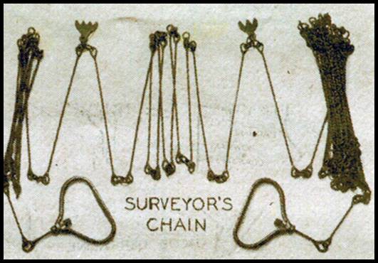
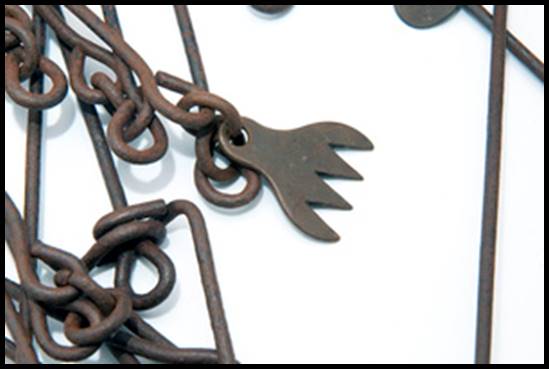
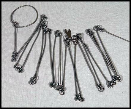
Examples of a Gunter’s or Surveyor’s chain showing its design and tags.
While Gunter’s, 4 pole chain became the recognised standard, other chains existed. William Leybourn in his 1653 publication, The Compleat Surveyor : or, The whole Art of Surveying of Land, wrote :
Of Chains there are divers sorts; as namely, Foot Chains, each Link containing a Foot or 12 Inches, and so the whole Pole or Perch will contain 16½ Links or Feet, answering to the Statute Denomination. Some Chains have each Pole divided into ten equal Parts, and these are called Decimal Chains, and this gross Division may be convenient in some Practices. The Chains now used and most esteemed by Surveyors, are especially two : Namely, that generally used by Mr Rathborne which hath every Perch divided into 100 Links; and that of Mr Gunter, which hath four Poles divided into 100 Links; so that each Link of Mr. Gunter's Chain is as long as four of Mr Rathborne's; and 50 Links of this Chain is two Pole, 25 one Pole, and 75 three Pole. Now, because these Chains are most esteemed of and used by Surveyors, I will therefore make a general Description of them both, leaving every Man at liberty to take his choice.
Of Mr Rathborne's Chain
The Chain which Mr Rathhorne ordinarily used (as himself saith) contained in length two Statute Poles or Perches, each Pole containing in length 16½ Feet, which is 198 Inches. Then each Pole was divided into 10 equal parts, called Primes, every of which contained in length 19 and 4/5 Inches. Again, every of those Primes was subdivided into 10 other equal parts, called Seconds, so that every of these Seconds contained in length 1 and 49/50 Inches, so that the Pole, Perch, Unite, or Commencement (as he calleth it) was divided into 100 equal parts or Links called Seconds. [Note that this made Rathborne’s 2 Pole chain 11 yards long and comprised of 200 links each link not quite 2 inches long].
Of Mr Gunter's Chain
As every Pole of Mr Rathborne's Chain was divided into 100 Links, so Mr Gunter's whole Chain (which is always made to contain four Poles) is divided into 100 Links; one of these Links being four times the length of the other [a Gunter Link was four times as long as a Rathborne Link]. Now, if this Chain be made according to the Statute, each Pole to contain 16½ Feet, then each Link of this Chain will contain 7 and 92/100 Inches, and the whole Chain 792 Inches, or 66 Feet.
John Eyre in his 1654 publication, The Exact Surveyor : or, The Whole Art of Surveying of Land, preferred a Rathborne type chain for the better avoyding many inconveniences…the Surveyour to have his Chain made of a good round wyre, not to containe above two Statute Poles or Perches, or three at the most, (which we will hereafter call an Unite) containeth in length 16 feete and a halfe, which is 198 inches… . Vincent Wing (1619-1668) a practicing surveyor, published in 1664, Geodaetes Practicus (The Art of Surveying). Therein, Wing described the use of a 4 pole (22 yards) chain divided into 80 links whereby every 2 links would equal one tenth of a pole [4 links would have been approximately 1 yard].
In his 1757 work The Art of Land-Measuring, John Gray stated that : the Chain, invented by Mr Edmund Gunter, about 150 years ago, is in length 22 yards, divided into 100 equal links, each link (consisting of a piece of iron or brass wire with a ring at each end) is 7.92 inches; every 10 links to 50 may be marked with a small plate of brass (or iron) of a different form, the 50th having a mark different from all the rest, 40 and 60 the same mark, for 30 and 70, 20 and 80, and 10 and 90. In imitation of this Chain, we have got a Scotch one, in length 24 ells, each link 8.88 Scotch inches [6 ells equalled 222 inches or 4 Scotch Rods and the Scottish ell was standardized in 1661 to 37 inches]. It is very proper, and even often necessary, for every Land-measurer to know so much of the making or constructing his instruments, especially of the graduated kind, as may enable him, not only to judge of their use and goodness, or accuracy of the workmanship, but also to give proper directions to any able workman, for making or mending them, when necessary, and even to put to a helping hand himself; I shall therefore here offer some observations and directions for that purpose…The links, or straight pieces of wire, should be all of them exactly of the same length; the wire should be soft, that it may bend any way easily, and not be, often exposed to the hazard of breaking, which will be unavoidable, if it is hard; the rings should also be all equal, but the wire of them hard, as well as the hooked ends of the links to which they are joined, that they may not easily draw out and be lost upon the ground, all the wire should be of the same thickness, about 1/10th of an inch; which I think is sufficient for strength, and it will be the easier carried about, and drawn along.
Later again came Jesse Ramsden’s (1735-1800) engineer’s, later railroad, chain, where the chain consisted of 100 links, but each one foot in length. The original of such 100 foot chains were constructed, to very high precision, for the measurement of the baselines of the Anglo-French Survey (1784–1790) and the Principal Triangulation of Great Britain. In France, after the French Revolution post circa 1800, and later in countries that had adopted the Metric System, 10 metre chains of 50 links each 200 millimetres long were used until the 1950s. A varra chain had 50 or 100 links and measured 10 or 20 varas [about 9 or 18 metres, respectively].
Use of the Chain
Arthur Burns an experienced surveyor, published in 1771 Geodaesia. Therein, in describing how to use of the chain for measuring Burns quotes from John Love’s 1688 work Geodaesia : Or the Art of Surveying and Measuring Land Made Easy : be sure that they who carry the chain, mistake not a chain either over or under, for if they should, the error would be very considerable.
The accepted procedure then, and carried forward while chaining was used to measure distance, until the mid 20th century was as Burns stated :
Let the Chain Leader be provided with ten small arrows about a foot long; though ten small wire pins (made sharp at one end, to enter the ground readily, and a noose at the other end, [later known as chaining arrows] to which a small piece of red cloth should be fastened, that it may thereby be more easily found in grass, etc.) would be much better in many respects. Let them be ten inches long, and let him that follows the chain, see that the Leader always puts down his arrow perpendicular, and in a direct line with the object he is going to, or bound for, which he may do by making him, at the end of every chain (before he puts down the arrow) cover or intercept the mark he is going to; for if he swerves from a right line, it will makes the distance longer than it really is, a right line being the shortest distance between two points. The Chain Leader and follower cannot be two careful in reckoning their arrows to each other at the end of every line, and every change; that is to say, the Measurer, or Chain Follower, must count ten arrows to the Leader at the end of every change; but if any should be missing, it is impossible to know who lost it, and therefore they must not only go back and find the lost arrow or arrows, but also measure the same line over again.
But to prevent all such mistakes, let him that leads the chain, take all the arrows in his left hand, and the chain upon the two first fingers of his right hand; then let him take one of the arrows into his right hand with the chain, and proceed to the place directed; and at the end of the chain let him stick the arrow down he held in his right hand, and take another out of his left hand; thus proceed until all the arrows are done; then the Measurer, or Chain Follower must carefully count the arrows to the leader, and if the line be any longer, proceed as above directed, always remembering the changes you have in each line, and at every change count the arrows, as above directed. If it be roads you measure note that 80 statute chains, make 1 mile.
First, upon the Chain Follower depends all the care of measuring, remarking, and noting down dimensions, &c. &c. and therefore it absolutely behooves every one that would be a Surveyor, to be not only particularly careful in his entries, and correct in his dimensions.
From this reconciliation of the chaining arrows after each 10 chains had been laid out, came the practice of noting this fact in what became known as a field book. The notations in the field book were thus 1 000 links, 2 000 links, or similar etc. Unfortunately, those reading these field books at a later time and not understanding the practice concluded that the chain used was of 1 000 links. Even if not understanding the practice, with a little thought in that a Gunter’s chain was said to weight between 3 and 6 pounds (4 pounds is about 2 kilograms), 10 chain would have weighed about 20 kilograms, the equivalent of a 10 litre bucket of water in each hand a significant load to anyone. Furthermore, based on a comment of the day they [chains] would be as cumbersome in their use as they were to manufacture, a 1 000 link chain would have been impractical, let alone unmanageable, ensuring some 3 000 individual components were kept straight.
The straight line distance of 179 miles, between London and York, was obtained by chaining between 1633-35 by Richard Norwood (1590-1665). Norwood was a resident in London, near Tower Hill, and a teacher of mathematics. Norwood is recorded as having used a chain of length 99 feet [6 poles or 33 yards] and his careful pace to obtain the road distance, removing the twists and turns. Norwood thus established that the length of one meridional degree of arc was 111.9 kilometres (111 kilometres today on a spherical earth).
As chains tended to lengthen with use, the distance laid out was thus less than true. It was reported that the : chain required frequent correction, as it was always lengthening through the links and rings becoming worn. This correction was generally performed by taking out one or more of the little rings, but the chain was generally kept an inch or so long. Anecdotally however, in pristine territory to ensure that parcels of land were never less than specified in area, a chain could even have 101 links. Over time, such generous allowances in land area could not be sustained and so to ensure the chain used for the day to day measuring operations did not get distorted, access to a second or reference chain was required. At least daily, the length of the working chain would be compared to that of the standard chain and the working chain’s length adjusted to that of the standard.
A circa 1880s Handbook, issued to South Australian Government Surveyors, stipulated the following regarding the chain and chaining : A Government Surveyor is supplied with two 100 link chains of 66 feet length. One is for daily use, and the other, which has been previously tested at the Survey Office, is kept as a standard. The working chain is compared with the standard every day by means of two pegs at the camp placed exactly a chain's length apart; which should be done morning or evening, when the thermometer stands at a mean temperature of about 60°F (approximately 16°C).
Determining the Angle between Two Intersecting Lines using only the Chain
Before accurate angular measurement became available to the general land surveyor a methodology was devised to determine the angle between two intersecting lines using only the chain. While likely already widely used, Love (1688) documented the solution.
First was to measure from the intersection point one chain (100 links) along each line, then measure the distance between the two end points at a chain’s distance from the intersection point.
Referring to his supplied table (see version below and diagram) if the measured distance between the two lines was 76 links then in the Links Column of the table find the nearest value to 76 links being 76 and 5 parts of a link, and alongside that value note the angle of 45 degrees. Thus the required angle is something less than 45 degrees. To find that remaining part of the angle see that one link and a half [actually 1.7 links but 1.5 is an easy multiple of 60] equals a degree [or 60 minutes], so that 5 parts of a link is some 20 minutes. The required angle therefore is 44° 40’.
|
CHORD LENGTH PER DEGREE OVER 100 LINKS |
|||||||||||
|
Degrees |
Links |
Degrees |
Links |
Degrees |
Links |
Degrees |
Links |
|
|||
|
1 |
1.7 |
36 |
61.8 |
71 |
116.1 |
106 |
159.7 |
|
|||
|
2 |
3.5 |
37 |
63.5 |
72 |
117.6 |
107 |
160.8 |
|
|||
|
3 |
5.2 |
38 |
65.1 |
73 |
119.0 |
108 |
161.8 |
|
|||
|
4 |
7.0 |
39 |
66.8 |
74 |
120.4 |
109 |
162.8 |
|
|||
|
5 |
8.7 |
40 |
68.4 |
75 |
121.8 |
110 |
163.8 |
|
|||
|
6 |
10.5 |
41 |
70.0 |
76 |
123.1 |
111 |
164.8 |
|
|||
|
7 |
12.2 |
42 |
71.7 |
77 |
124.5 |
112 |
165.8 |
|
|||
|
8 |
14.0 |
43 |
73.3 |
78 |
125.9 |
113 |
166.8 |
|
|||
|
9 |
15.7 |
44 |
74.9 |
79 |
127.2 |
114 |
167.7 |
|
|||
|
10 |
17.4 |
45 |
76.5 |
80 |
128.6 |
115 |
168.7 |
|
|||
|
11 |
19.2 |
46 |
78.1 |
81 |
129.9 |
116 |
169.6 |
|
|||
|
12 |
20.9 |
47 |
79.7 |
82 |
131.2 |
117 |
170.5 |
|
|||
|
13 |
22.6 |
48 |
81.3 |
83 |
132.5 |
118 |
171.4 |
|
|||
|
14 |
24.4 |
49 |
82.9 |
84 |
133.8 |
119 |
172.3 |
|
|||
|
15 |
26.1 |
50 |
84.5 |
85 |
135.1 |
120 |
173.2 |
|
|||
|
16 |
27.8 |
51 |
86.1 |
86 |
136.4 |
121 |
174.1 |
|
|||
|
17 |
29.6 |
52 |
87.7 |
87 |
137.7 |
122 |
174.9 |
|
|||
|
18 |
31.3 |
53 |
89.2 |
88 |
138.9 |
123 |
175.8 |
|
|||
|
19 |
33.0 |
54 |
90.8 |
89 |
140.2 |
124 |
176.6 |
|
|||
|
20 |
34.7 |
55 |
92.3 |
90 |
141.4 |
125 |
177.4 |
|
|||
|
21 |
36.4 |
56 |
93.9 |
91 |
142.7 |
126 |
178.2 |
|
|||
|
22 |
38.2 |
57 |
95.4 |
92 |
143.9 |
127 |
179.0 |
|
|||
|
23 |
39.9 |
58 |
97.0 |
93 |
145.1 |
128 |
179.8 |
|
|||
|
24 |
41.6 |
59 |
98.5 |
94 |
146.3 |
129 |
180.5 |
|
|||
|
25 |
43.3 |
60 |
100.0 |
95 |
147.5 |
130 |
181.3 |
|
|||
|
26 |
45.0 |
61 |
101.5 |
96 |
148.6 |
131 |
182.0 |
|
|||
|
27 |
46.7 |
62 |
103.0 |
97 |
149.8 |
132 |
182.7 |
|
|||
|
28 |
48.4 |
63 |
104.5 |
98 |
150.9 |
133 |
183.4 |
|
|||
|
29 |
50.1 |
64 |
106.0 |
99 |
152.1 |
134 |
184.1 |
|
|||
|
30 |
51.8 |
65 |
107.5 |
100 |
153.2 |
135 |
184.8 |
|
|||
|
31 |
53.4 |
66 |
108.9 |
101 |
154.3 |
136 |
185.4 |
|
|||
|
32 |
55.1 |
67 |
110.4 |
102 |
155.4 |
137 |
186.1 |
|
|||
|
33 |
56.8 |
68 |
111.8 |
103 |
156.5 |
138 |
186.7 |
|
|||
|
34 |
58.5 |
69 |
113.3 |
104 |
157.6 |
139 |
187.3 |
|
|||
|
35 |
60.1 |
70 |
114.7 |
105 |
158.7 |
140 |
187.9 |
|
|||
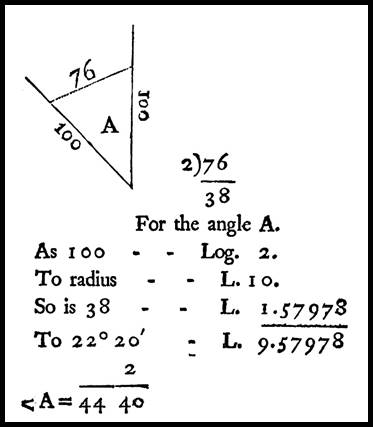
As Gray (1757) later showed in the diagram above that the Sine of half the required angle equals the ratio of half the distance between the two end points to the radius 100. Gray’s more sophisticated result required the knowledge and use of logarithms.
Thus, with only his chain, a Surveyor could measure distance and determine any angles, to better than plotting/mapping accuracy.
The Evolution and End of the Chain
The chain of iron/wire links was replaced by a thin, narrow, ribbon of steel of both 66 and 100 feet in length. The steel band as it was known required less maintenance than the wire link chain and was less prone to distortion. Steel was later replaced by a nickel-steel alloy invented by Swiss physicist and metrologist Charles Édouard Guillaume in 1896, named Invar for its Invariability under extremes of heat or cold; its coefficient of expansion was 15 times less than that of steel. Invar bands could be up to 300 metres in length. Despite this evolution steel and Invar bands required calibration from time to time using an accurately set out calibration range that met the national standard of accuracy. These ranges were often in basement rooms or corridors or at least undercover away from direct sunlight where the temperature could be considered constant.
Electro-optic measurement systems have today largely replaced the need to have access to the intervening ground between two points. Nevertheless, even these sophisticated tools have to be calibrated against the national standard to ensure their readings meet the accuracy requirement of the work.
by Paul Wise, 2023.
Sources
Atwell, George (1658), The Faithfull Surveyour, Cambridge or London, accessed at : https://quod.lib.umich.edu/e/eebo/A26162.0001.001?view=toc
Brewster, David (1832), The Edinburgh Encyclopaedia, Vol.12, Philadelphia.
Burns, Arthur (1771), Geodaesia Improved : Or a New and Correct Method of Surveying Made Exceedingly Easy, Chester, accessed at : https://books.google.com.au/books/about/Geodaesia_Improved_Or.html?id=iSg1AAAAMAAJ&redir_esc=y
Chambers, Ephraim (1728), Cyclopaedia: or, An Universal Dictionary of Arts and Sciences, London, accessed at : https://archive.org/details/Cyclopediachambers-Volume1 ; https://archive.org/details/Cyclopediachambers-Volume2
Clarke, Alexander Ross (1866), Comparison of Standards of Length : England, France, Belgium, Prussia, Russia, India, Australia, London, accessed at: https://pahar.in/wpfb-file/1866-comparison-of-standards-of-length-of-england-france-belgium-prussia-russia-india-australia-by-clarke-s-pdf/
Eyre, John (1654), The Exact Surveyor : or, The Whole Art of Surveying of Land, London, accessed at : https://books.google.com.au/books/about/The_Exact_Surveyor_Or_the_Whole_Art_of_S.html?id=AmlnAAAAcAAJ&redir_esc=y
Gray, John (1757), The Art of Land-Measuring Explained, Glasgow, accessed at : https://books.google.com.au/books/about/The_Art_of_Land_Measuring_Explained_with.html?id=DGNXIFq0Rl8C&redir_esc=y
Gunter, Edmund (1673, Ed.5), The Works Edmund Gunter, first published 1623, London, accessed at : https://ia601009.us.archive.org/35/items/worksofedmundgun00gunt/worksofedmundgun00gunt.pdf
Hill, Donald (1996), A History of Engineering in Classical and Medieval Times, Routledge (first published 1984).
Hopton, Arthur (1611), Speculum Topographicum, or The Topographicall Glasse, London, accessed at : https://ota.bodleian.ox.ac.uk/repository/xmlui/handle/20.500.12024/A03653#
Leybourn, William (1653), The Compleat Surveyor : or, The whole Art of Surveying of Land, London, accessed at : https://books.google.com.au/books?id=aHzmAAAAMAAJ&printsec=frontcover&redir_esc=y#v=onepage&q&f=false
Love, John (1792, Ed.11), Geodaesia : Or the Art of Surveying and Measuring Land Made Easy, first published 1688, London, accessed at : https://books.google.com.au/books/about/Geodaesia.html?id=mWZkAAAAMAAJ&redir_esc=y
Nicholson, Edward (1912), Men and Measures, London.
Rathborne, Aaron (1616), The Surveyor in Foure Bookes, W Stansby, accessed at : https://books.google.com.au/books/about/The_Surveyor_in_Foure_Bookes_by_Aaron_Ra.html?id=KIM4cgAACAAJ&redir_esc=y
Smellie, William (1771, Ed.1), Encyclopaedia Britannica, Edinburgh, accessed at : https://digital.nls.uk/144133903
Wing, Vincent (1664), Geodaetes Practicus : The Art of Surveying, London.